Go to HOMEPAGE

Problem description:
In my brothers Renault dealership a Facom GTR300 tool is used for wheel allignment measurements/adjustments. The matrix printer has failed a long time ago (which is not surprising in the dusty environment of a garage).
The GTR300 was connected to the printer through a classic printer cable, with a DB-25 connecter on the PC end, and the 36 pin micro ribbon Centronics connector on the printer side.

I first attempted if a standard HP Laserjet 2100 (with Postscript emulation dimm) would be able to interpret the GTR300 output correctly. This resulted in a page with some unreadable characters at the top of the page, and some lines of readable text. So apparently the output of the GTR is a language which is relatively close to standard ASCII text.

My collegue and friend Jos van Heck had the great idea to start a little project, using the Raspberry Pi GPIO pins to extract the data from the GTR parallel port, interpret the data from the GTR, and send it over WLAN to one of the network printers.

First night at Jos's, we got together to learn the basics of the Raspberry's GPIO pins. We got a flying start using The MagPi Issue 7 (pages 12-15). Something which is also described here in detail.
Using a circuit board from Jos's collection, we first tried if we could get one GPIO pin to light up a LED. ("Hello world" for IO). Using a LED, and a 270Ω resistor in series, connected between pin 16 (GPIO23) and 6 (GND). Then on the command shell we used the following commands to make the connected led go on and off:
echo 23 >/sys/class/gpio/export
echo out >/sys/class/gpio/gpio23/direction
echo 1 >/sys/class/gpio/gpio23/value
echo 0 >/sys/class/gpio/gpio23/value
A picture of the flat cable wiring pin 16 and 6 is displayed in the picture in the next text box.

After this first succes, we wanted to see if we could get the Raspberry Pi to respond to an input signal. Now the parallel printer port operates at a level of 5V, whereas the Raspberry Pi GPIO operates at a level of 3.3V.
Jos already had experience with ULN2003 hardware (Darlingtons) and had some of these at home (in the cabinet labled U for ULN  ;-) ). We used the circuit board to test this configuration, where we first used the +3.3Vpin of the Raspberry Pi, to set an input signal on the ULN2003.
A poor man's sketch of the board looks like this:

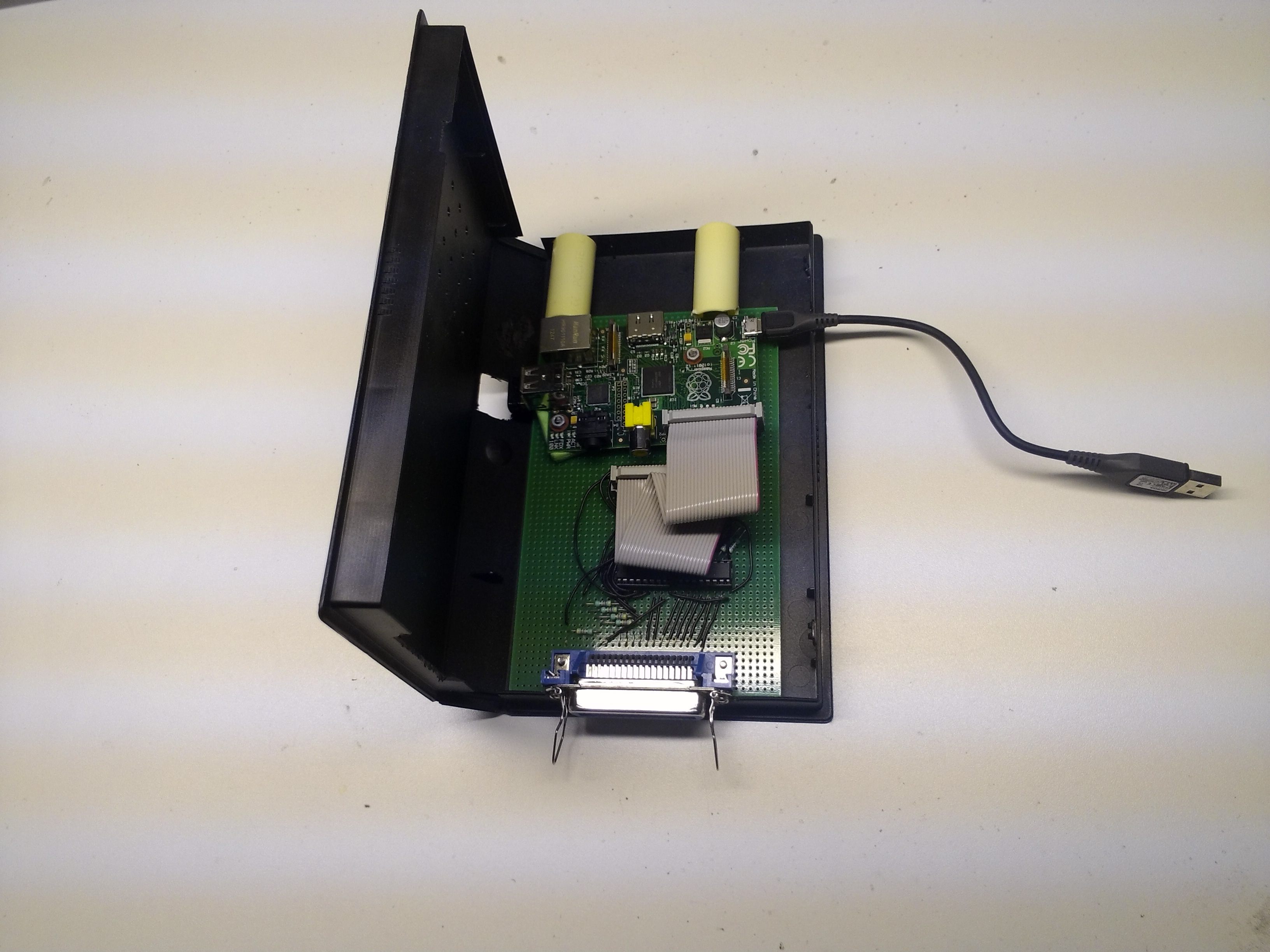
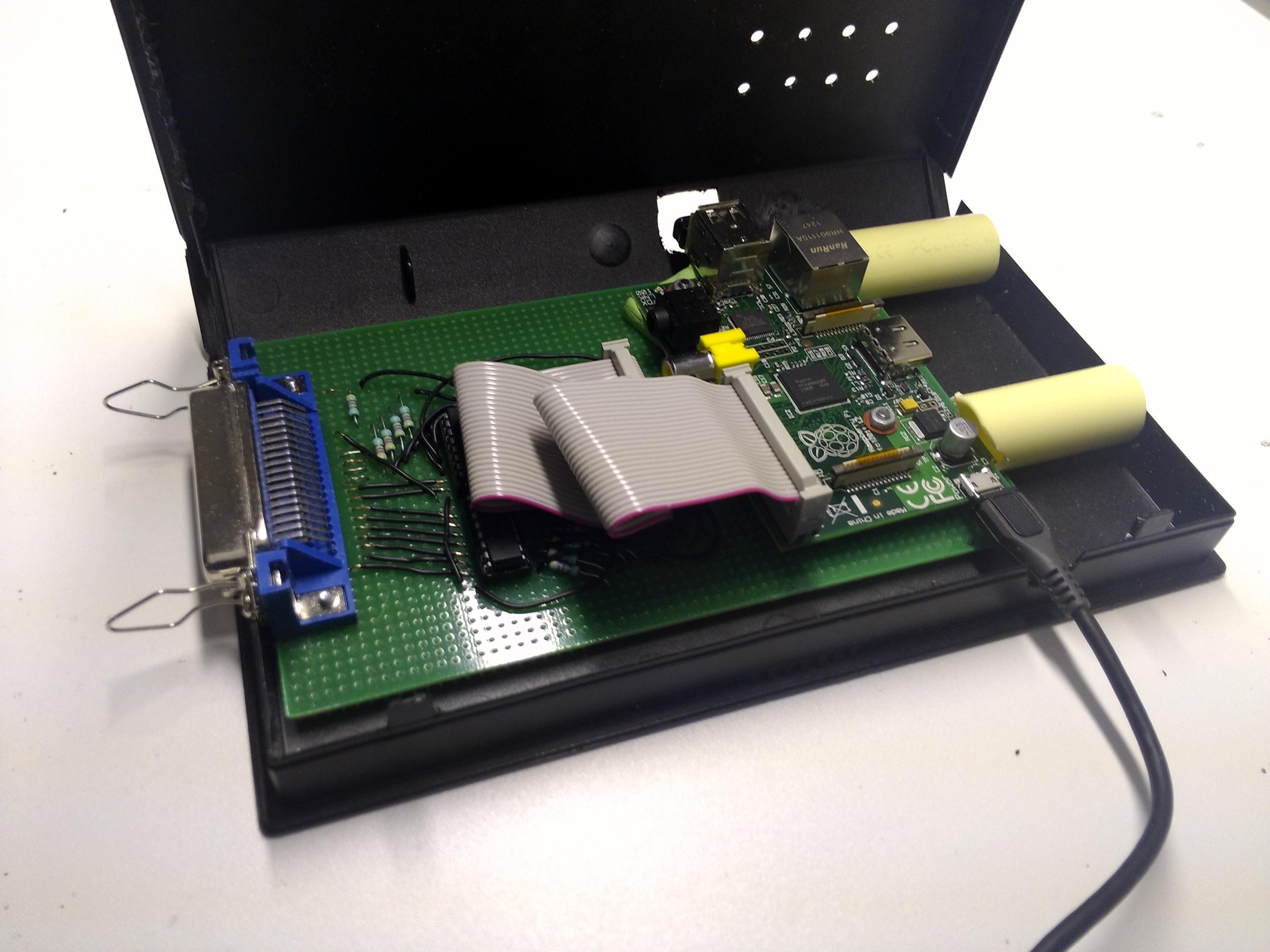
A picture, where you can see the flatcable, with pins 1, 6 and 16 connected to the board:

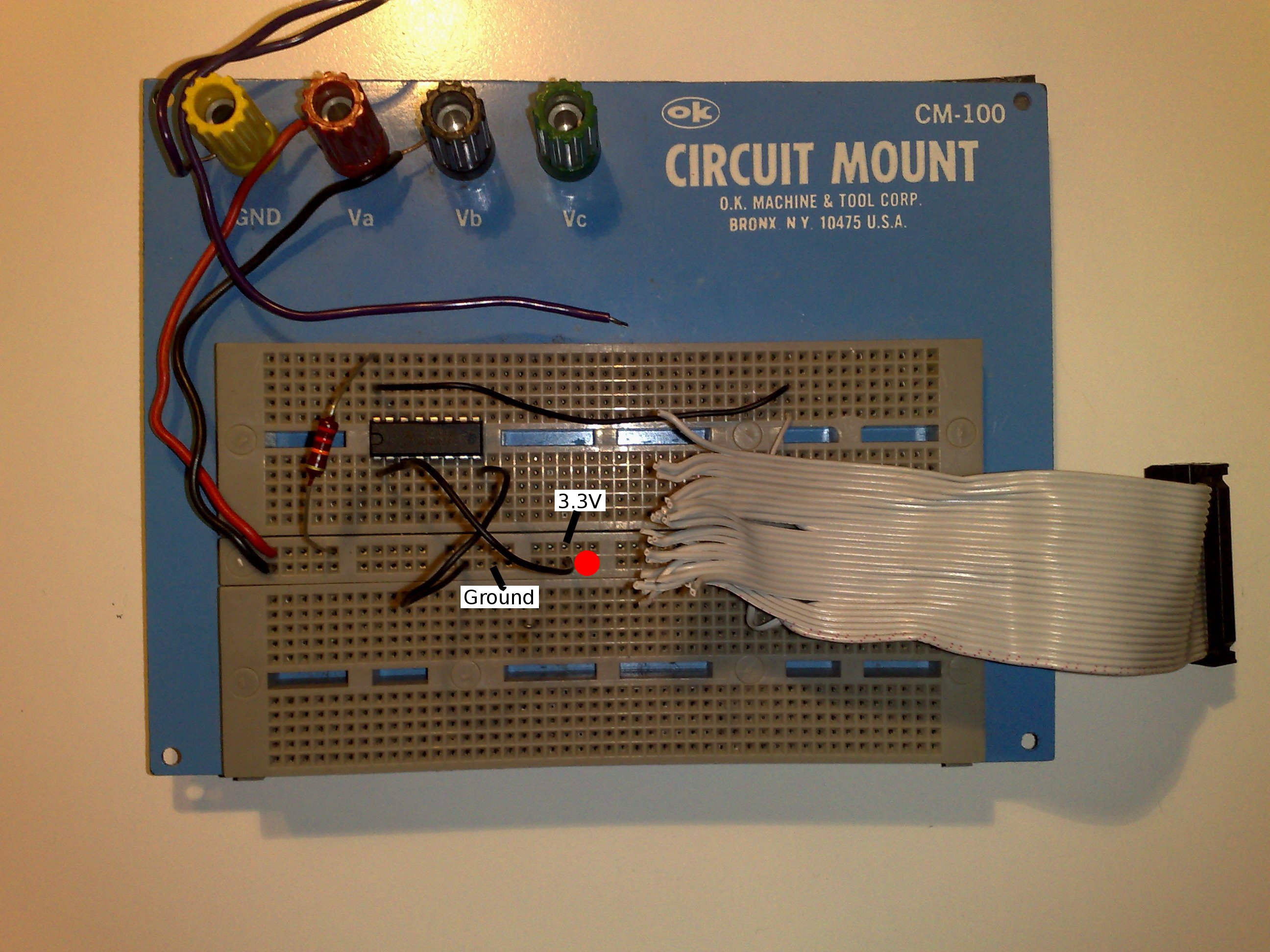
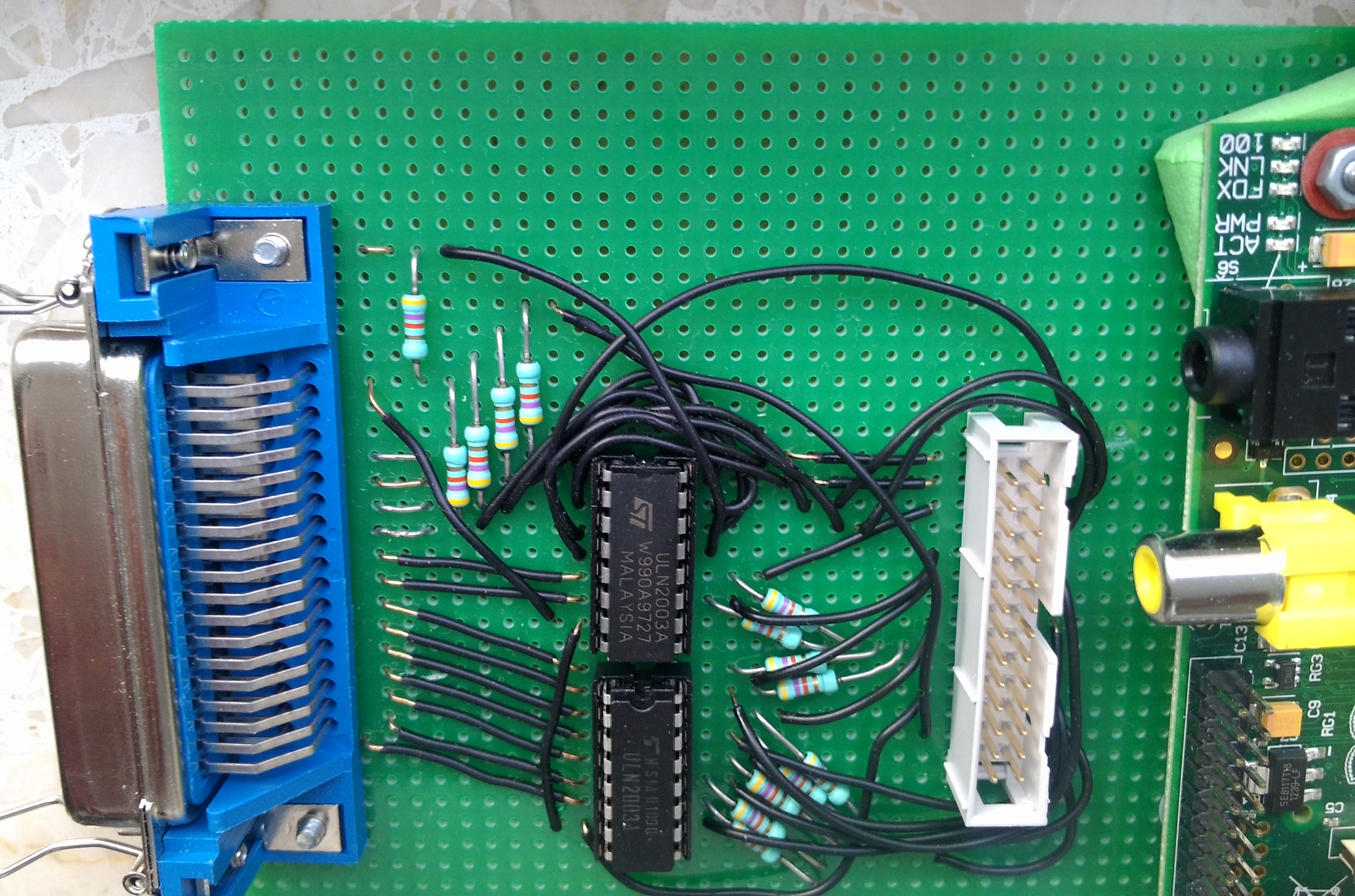
The photo shows the situation where the lower left pin of the ic is connected to ground. It can be switched to +3.3V by moving the black wire one hole up from it's current location (indicated by red dot in the image).
Be sure to set GPIO pin 23 to IN before you connect the Raspberry:
echo in >/sys/class/gpio/gpio23/direction
Once all is connected, you can see if the pin sees an input of 0 or 1 by giving the command:
cat
/sys/class/gpio/gpio23/value

Secondly, we disconnected pin 6 from the board, and instead succesfully used an external power supply to supply 5V input level, as sketched below:

This concluded the experiments on the first night.

Then I started working on a print to connect all relevant pins of the printer port. A description of the Centronics printer protocol can be found here. An overview of all relevant pins is also here & here.
I created the print according to the following scheme:

I used the 5V power from the Raspberry, since the Centronics specification is not clear on always having a +5V pin available. All GND pins on the 36pin side have been connected to each other, and also to the Raspberry GND pin. The print looks like:


In the end 9 signals are going from the GTR300 computer to the GPIO pins of the raspberry:
- 1 strobe signal
- 8 x 1 bit signal (=1 byte)
 And 5 pins are going in the oposite direction to tell the computer (GTR) about the status of the printer (RaspberryPi):
- acknowledge
- busy
- paper out
- select
- error

I'll skip a lot of the experimenting we did to check if everything was working correctly. I'll only add some of the test scripts we used. After connecting the new piece of hardware, we checked if we could read the PC output. We defined a generic text printer on the PC and send a simple text document to it. We used this script to define the pins. Then manually experimented with setting the output values (0/1) on pins 7-11:
echo 1 >/sys/class/gpio/gpio7/value
echo 0 >/sys/class/gpio/gpio7/value
echo 1 >/sys/class/gpio/gpio8/value
echo 0 >/sys/class/gpio/gpio8/value
etc, until pin 11.

It appeared that the Centronics documentation could be used perfectly to determine the correct value of the output pins. Just don't forget to invert all in-/output values, because the ULN2003 circuit inverts all signals.
We were able get the printing process going, and saw that the input pins showed changing values using this script.

For some reason we were not able to get the process running on Jos' PC. The print process did not continue after the first byte. This might have been caused by the BIOS settings on his PC, but we haven't checked this. At home on one of my old PC's (with printer port) the process did work as expected.

With the hardware working, the software could be writtten. Programming is done in C, using Gordon's WiringPi tools.
After running some tests, I made a small adjustment to two routines in wiringPi.c: interruptHandler & waitForInterrupt. The modification clears the interrupt, only after the full interupt function has been handled. The original setup allowed for a second interrupt to be triggered before the first one is finished. However, the application I am setting up proved to fail anyway if a strobe intterupt occurs before the previous has finished. It simply results in twice the same character. This modification makes the routine more clear, and also allows for the Osciloscope function to respond only to the first interrupt detected (the function will be explained in the next section).
By the way: In the end, the parallel port of my old PC appeared to send data too fast, even too fast to set the busy bit high (which would put the PC output on hold). Fortunately the GTR-300 sends data slow enough for the Raspberry to keep up.

Modifications to WiringPi are minor. In "wiringPi.c" only two functions are modified: "waitForInterrupt", and "interruptHandler". Since I changed the function arguments of "waitForInterrupt", the "wiringPi.h" is modified accordingly.
Here's a copy of the wiringPi library as I cloned it at the time from Gordon's github. Here are the modified files.

Using "isr.c" from Gordon's wiringPi example directory, I created the function Oscilloscope.c. This function helps to detect what printing language to expect from the PC (or GTR300).
Here's the function. And here is an example of the output files that you can expect.

In order to develop the processing routines, it is convenient to be independend of the printing device (GTR-300). The output from the printing device is captured in a binary file by running this c-function.

The GTR-300 printer output matches the epson printer format as described here. The initial data from the GTR-300 defines the variable tab locations (with the character width as a basis). The output contains one set of fixed tab locations for the whole document. The format is closely related to the fixed fontwidth format of a conventional typewriter.
After a little investigation, I found that LibreOffice Writer is able to define a document in the same manner. This means LibreOffice can be conveniently used to simply define the fixed tab widths once, and for the rest simply translate each printed charachter (including the tab characters) one by one.
Fortunately LibreOffice Writer also enables the use of double width characters, as they are present in the document printed by the GTR-300.
LibreOffice Writer supports OTD documents in Flat-XML format. By creating a simple document in LibreOffice and writing this out in Flat-XML format it was not hard to reverse-engineer the code that I needed for the special characters that are used in the GTR-300 prints. Interesting to know that a 12pt font heigth for "liberation Mono" font means a 7.2 pt fontwidth. This is relevant to define the tab positions in nr of points.
I created a standard template (consisting of three fileparts). The eps_convert.c routine creates two pieces of xml code which will be combined with the three template sections into one document.
The routine to read the data from the parallel port has practically remained the same:

The runprinter routine needs to be added to the /etc/rc.local file, so it executes automatically when the Raspberry is started.
The compiled 'Runprinter' routine, together with the files 'part1', 'part2' and 'part3', must be placed in /usr/local/runprinter.

With this function running, the raspberry needs to be set up in a normal way:
- wifi network (in my case: interfaces, wlan, wpa)
- default printer (network printer, can be defined via CUPS, localhost:631. Lowriter automatically prints to default printer)
- disable unneccessary services (ssh)

Now in order to be able to mount the Raspberry's SDcard read only, a couple of simple modifications need to be made to /etc/fstab. Mainly adding a couple of tmpfs filesystems for folders which require write access. The root folder must be added, because lowriter requires write access to the user's home folder.

Remarks:
Initially I ran into problems when I switched the mmcblk0p2 device to read only. I used the formidable debuggin utility 'strace' to find out what was going on in lowriter. It appeared that at a certain point 'lowriter' was trying to write in the '/' folder. I noticed that for lowriter to function correctly, it requires a temporary folder in the users home directory. When running runprinter from rc.local, the process is running as root and no user environment settings are defined. That's why the following environment settings had to be added  to the 'lowriter' call in above-mentioned Runprinter.c:
HOME=/root USERNAME=root USER=root LOGNAME=root
That is also the reason that /root was added as a tmpfs to fstab.

With these settings, the mmcblk0p2 device can be set to read only.

Now everything is put in a nice box (old VHS):


Some local hardlinks:
The Epson printer codes.
MagPi issue 7.

Go to HOMEPAGE